

Identifying and Solving Thermal Bridging in Domestic Buildings
Some rooms have a corner that never feels warm, a cold strip above a window, or a line of black spots where the ceiling meets the outside wall. Very often the cause is thermal bridging: a place where the structure gives heat a short cut from the warm inside to the cold outside.
Thermal bridging in domestic buildings matters most in the heating season, because that is when the difference between inside and outside is large enough for a bridge to do harm. Heat flows faster through the bridge than through the insulated wall around it, so the inside surface at that spot runs cooler than the rest of the room. A cooler surface is where moisture in the room air settles first, which is why bridges so often sit behind the mould at a window head or a ceiling corner. They also add to heat loss and make a room feel colder than the thermostat says. None of this is visible to the eye until the damage shows, but it is visible to a calibrated radiometric thermal camera, because a bridge leaves a pattern that follows the structure of the building.
This post is for homeowners, landlords and anyone who has extended or altered a home and wants to know whether the junctions are performing. It explains what a thermal bridge is, how it shows on a thermal image, why it matters, what can look like one but is not, and who to call once one is found. Thermography Services (UK) surveys, analyses and reports; the building work is for the right trade.
Thermal Bridges in Homes and Why They Matter
Cold corners, damp window heads and chilly floor edges often share one structural cause.
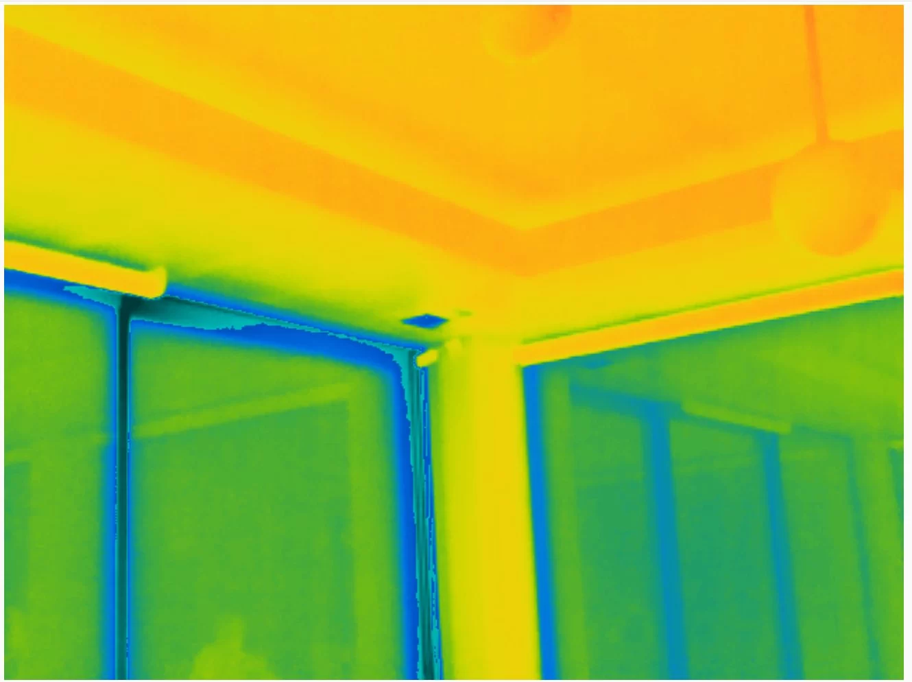
How a Thermal Bridge Shows
What a thermal bridge is
A wall, roof or floor is built to slow the flow of heat. Most of its area does that well. A thermal bridge is the small part that does not: a lintel over a window, the edge of a floor slab, a steel beam, a timber stud or a frame that carries heat through, or past, the insulation. Heat flow concentrates there because the material conducts heat more readily than the insulated construction around it.
The result is simple to describe. On the outside, the surface over the bridge is a little warmer than the wall around it, because more heat is arriving. On the inside, the surface is a little cooler, because more heat is leaving. A thermal camera sees both. It does not see the steel or the concrete; it sees the surface temperature pattern the bridge creates.
Where bridges sit in a home
Bridges sit where the structure changes, which is why a survey gives junctions their own frames. The usual places are:
- window and door heads, where a lintel spans the opening
- window and door reveals and the joint between frame and wall
- the edge of an intermediate floor, where it bears on the outside wall
- the junction of wall and roof at the eaves, and wall and ground floor at the base
- external corners
- balconies, parapets and any change of material
- the line where an extension meets the original house
How a bridge looks on a thermal image
A thermal bridge has a shape, and the shape is the first clue. Because it follows the structure, it is usually linear and regular: a band along a floor edge, a strip over each window head at the same height, a line up a corner from ground to roof. It repeats wherever the same detail repeats. That regularity is what separates it from the other two patterns a building envelope survey looks for.
Air leakage looks different. Moving air cools the surface around a gap in a feathered, directional pattern that spreads from a seal, a joint or an opening. Missing or displaced insulation looks different again: a patch with its own outline, often unrelated to the structure, where a whole area of wall or ceiling runs warmer outside or cooler inside. One image can hold all three, and the analysis classifies each feature on its own evidence.
Why it matters: cold surfaces and condensation
The heat lost through a single bridge is small. The more practical problem is the cold inside surface. Room air carries moisture from cooking, washing, drying clothes and breathing. When that air meets a surface cold enough, the moisture condenses on it. A bridge creates exactly that surface, in a fixed place, every cold night.
That is why mould so often starts in the same spots: the top corner of an outside wall, the head of a window, behind a wardrobe on an outside wall where the air cannot circulate. A thermal image that shows a cool band at that junction indicates that the surface is a likely place for condensation to form. It does not prove that mould will grow, because ventilation, heating and how the room is used all play a part, but it explains why a problem keeps coming back after the wall has been cleaned and repainted.
Comfort is the third effect. A cold strip of wall or ceiling draws radiant heat from the people in the room, so the room can feel cooler than the air temperature suggests.
What else can look like a bridge
Not every cool line is a defect. External corners are the clearest example. At a corner the outside face is larger than the inside face, so the inside of a corner always runs a little cooler, even when it is well built. The analysis asks whether the pattern is stronger than the geometry explains, and compares it with the other corners of the same building.
Other look-alikes come from outside the fabric. A radiator behind a wall warms it; a vent or boiler flue throws a warm plume; sunshine earlier in the day leaves a face warm for hours; a wet patch from rain cools by evaporation; glazing and shiny surfaces reflect the temperature of whatever faces them. This is why the survey runs after dark or before sunrise, with at least 10 °C between inside and outside held for 12 hours, why every thermal frame has a matching visual photograph, and why the operator walks round first and notes every vent, flue, light and recent repair.
What two surveys showed
On a pre-cast concrete panel residential block in Scotland, surveyed as a baseline before refurbishment, continuous thermal bridges ran the full height of both north-facing corners. That is a structural pattern: it runs the full height and repeats on both corners, so it reads as a bridge rather than a local fault.
On a bungalow in Surrey, surveyed ahead of an architectural redesign, the imaging showed thermal bridging and air leakage indicators together at the interfaces between window frames and walls. Two causes at one detail is common, and separating them is part of the analysis, because a builder treating a frame joint needs to know which one is present.
From finding to the right trade
The title of this post talks about solving thermal bridging. The solving belongs to the people who design and build. A thermographic survey finds and explains; it never prescribes a repair. What it gives you is the location, the extent and the likely cause of each pattern, so that the right person is asked the right question.
A bridge at a lintel or a floor edge is a question for an architect, a building surveyor or a builder, since the answer depends on the construction. A frame joint is a question for the window installer. A bridge where an extension meets the house goes back to whoever designed or built the extension. A follow-up survey under the same conditions can then show whether the pattern has changed after the work.
What the report gives you
Every feature is classified (thermal bridging, air leakage, insulation missing or deficient, or heat loss where the mechanism cannot be isolated) and given a severity from Advisory to High, with the thermal image, the matching photograph and the conditions on the night. The analysis is qualitative: it shows surface patterns and what they are consistent with, and it does not calculate U-values. Every report is written and certified by our Level 3 thermographer. If you want the junctions of your own home checked, a thermal bridging survey covers the envelope inside and out, with every junction imaged in its own frame.
BS EN ISO 6781-1:2023
Reading Bridges at Junctions
BS EN ISO 6781-1:2023, Performance of buildings, Detection of heat, air and moisture irregularities in buildings by infrared methods, Part 1: General procedures, is the current standard for building envelope thermography. It replaced BS EN 13187:1999. Its title names the three things a survey looks for, heat, air and moisture irregularities, and a thermal bridge is a heat irregularity in that sense. It sets out the general procedure: a steady temperature difference across the envelope, no solar loading on the surveyed faces, reference temperatures recorded, and the conditions written into the report. The method is qualitative. It identifies surface patterns consistent with a bridge and locates them on the building, but it does not measure the heat flow through a junction or calculate a U-value. Our building surveys are aligned with its general procedures, with every junction imaged in its own frame and matched to a visual photograph.

Check Your Home's Junctions
If a corner, a window head or a floor edge in your home stays cold or keeps growing mould, a thermal image can show whether a thermal bridge sits behind it. Thermography Services (UK) surveys inside and out under recorded conditions, images every junction in its own frame, and explains each pattern, with the right trade to ask. Every report is written and certified by our Level 3 thermographer. Tell us about the property and we will quote.